在“测定金属丝的电阻率”的实验中,实验室提供以下器材:
A.电源E:电动势约为 ,内阻约
,内阻约 ;
;
B.电流表 :量程为
:量程为 ,内阻
,内阻 ;
;
C.电流表 :量程为
:量程为 ,内阻约为
,内阻约为 ;
;
D.定值电阻 ;
;
E.定值电阻 ;
;
F.滑动变阻器R:最大阻值 ;
;
G.开关S一个,导线若干:
H.螺旋测微器。
(1)请根据方框丁内的部分电路,合理选用所给器材,补全测量金属丝电阻 (阻值约为
(阻值约为 )的电路,要求在电路图上注明所选元件符号
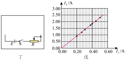
(2)用设计的电路进行实验,获得多组电流表 和
和 的读数
的读数 ,描点作图得到如图戊所示的图像,可以算出金属丝的电阻
 (计算结果保留一位小数)。
(3)若金属丝的长度为L,直径为d,则该金属丝的电阻率 、π、L、d表示)。
更新时间:2024-01-21 13:10:10
|
相似题推荐
实验题
|
适中
(0.65)
【推荐1】电导率是电阻率的倒数,是检验纯净水是否合格的一项重要指标.某学习小组对某种纯净水样品的电导率进行检验。
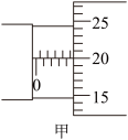
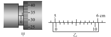
(1)将采集的水样装满绝缘的圆柱形塑料容器,两端用金属圆片电极密封,用螺旋测微器测量该容器的直径,如图甲所示,则容器直径的测量值d=______ mm.
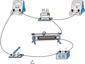
(2)为更精确地测量所取水样的电阻,该小组从实验室中找到如下实验器材:
A.电流表(量程3mA,电阻约为5Ω)
B.电压表(量程6V,电阻约为10kΩ)
C.滑动变阻器(0~20Ω,额定电流1A)
D.电源(6V,内阻约为1Ω)
E.开关一只、导线若干
请用笔画线代替导线,把图乙中测量纯净水样品电阻的电路补充完整______
(3)正确连接电路后,闭合开关,调节滑动变阻器,记录电压表示数U和电流表示数I如下表:
请根据表中的数据,在图丙的方格纸上作出纯净水样品的U-I图线______ 。
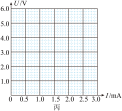
(4)根据U-I图线可得纯净水样品的电阻为______ Ω。(结果保留两位有效数字)
(5)不合格的纯净水比合格的纯净水的电导率______ (选填“大”或“小”)。
(1)将采集的水样装满绝缘的圆柱形塑料容器,两端用金属圆片电极密封,用螺旋测微器测量该容器的直径,如图甲所示,则容器直径的测量值d=
(2)为更精确地测量所取水样的电阻,该小组从实验室中找到如下实验器材:
A.电流表(量程3mA,电阻约为5Ω)
B.电压表(量程6V,电阻约为10kΩ)
C.滑动变阻器(0~20Ω,额定电流1A)
D.电源(6V,内阻约为1Ω)
E.开关一只、导线若干
请用笔画线代替导线,把图乙中测量纯净水样品电阻的电路补充完整
(3)正确连接电路后,闭合开关,调节滑动变阻器,记录电压表示数U和电流表示数I如下表:
| U/V | 1.1 | 1.8 | 2.8 | 2.9 | 3.7 | 4.7 |
| I/mA | 0.50 | 0.82 | 1.05 | 1.38 | 1.73 | 2.20 |
(4)根据U-I图线可得纯净水样品的电阻为
(5)不合格的纯净水比合格的纯净水的电导率
您最近一年使用:0次
实验题
|
适中
(0.65)
名校
【推荐2】某同学设计实验“测定金属的电阻率”,要求电压从零开始调节。已知金属丝的电阻大约为,在用伏安法对金属丝电阻进一步测定时,有如下实验器材可供选择:
直流电源:电压3V,内阻不计:
电流表A:量程0~0.6A,内阻 :
:
电压表V:量程0~3V,内阻约 ;
;
滑动变阻器 :最大阻值
:最大阻值 ;
;
滑动变阻器 :最大阻值
:最大阻值 ;
;
开关、导线等。
(1)用螺旋测微器测金属丝的直径时,如图甲所示,可知金属丝的直径

(2)在所给的器材中,滑动变阻器应选
(3)根据题目要求和实验器材,为了减小误差,实验电路图应选
A.
 B.
B. C.
C. D.
D.
您最近一年使用:0次
实验题
|
适中
(0.65)
【推荐3】如图一所示是某磁敏电阻在室温下的电阻 随磁感应强度B变化的特性曲线,其中,在0.4T≤B≤1.2T的范围内,图线为直线.测试时,磁敏电阻的轴向方向与磁场方向垂直.

(1)试结合图一,写出在0.4 T≤B≤1.2 T的范围内,随B变化的关系式= _______ .
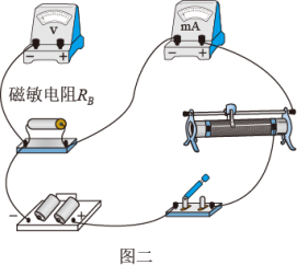
(2)某同学想利用该磁敏电阻去测量某磁场的磁感应强度B,他找到了如图二所示的器材,并连好部分导线.
①该同学所选器材的规格为:电源(电动势3 V,内阻不计);磁敏电阻(无磁场时的阻值 Ω);滑动变阻器(最大电阻约10Ω);电流表(量程2.5mA,内阻约10Ω);电压表(量程3V,内阻约3kΩ).
请在图二中用笔画线代替导线将磁敏电阻接入电路,并能在实验中,调节滑动变阻器滑片时得到如下表所示的数据:( )
②忽略电路中电流产生的磁场,根据表中数据和上述信息,求出所测磁场的磁感应强度B的大小为__________ T. (取一位有效数字)
随磁感应强度B变化的特性曲线,其中,在0.4T≤B≤1.2T的范围内,图线为直线.测试时,磁敏电阻的轴向方向与磁场方向垂直.(1)试结合图一,写出在0.4 T≤B≤1.2 T的范围内,
随B变化的关系式= (2)某同学想利用该磁敏电阻去测量某磁场的磁感应强度B,他找到了如图二所示的器材,并连好部分导线.
①该同学所选器材的规格为:电源(电动势3 V,内阻不计);磁敏电阻(无磁场时的阻值
Ω);滑动变阻器(最大电阻约10Ω);电流表(量程2.5mA,内阻约10Ω);电压表(量程3V,内阻约3kΩ).请在图二中用笔画线代替导线将磁敏电阻接入电路,并能在实验中,调节滑动变阻器滑片时得到如下表所示的数据:
| 1 | 2 | 3 | 4 | 5 | 6 | |
 | 0.00 | 0.45 | 0.91 | 1.50 | 1.79 | 2.71 |
 mA mA | 0.00 | 0.30 | 0.60 | 1.00 | 1.20 | 1.80 |
②忽略电路中电流产生的磁场,根据表中数据和上述信息,求出所测磁场的磁感应强度B的大小为
您最近一年使用:0次
实验题
|
适中
(0.65)
【推荐1】在测量电阻的实验中,提供的器材有:3V稳压电源E、滑动变阻器R、电压表V、电流表A、待测电阻Rx,以及开关S、导线等。
实验要求:
①电流表内接;②调节滑线变阻器可使电压表的示数在0~3V间变化.
(1)在实验中,有的同学连成如图所示的电路,其中a,b,c,…,k是表示接线柱的字母.请将图中接线错误(用导线两端接线柱的字母表示)、引起的后果、改正的方法(用“改接”、“撤销”或“增添”等词语描述),分别填在相应的表格中________________________ 。

(2)实验中所用电压表的内阻约为20kΩ,电流表的内阻约为10Ω,按正确的电路操作,读得的各组数据用+标于坐标图上,如图所示.根据各点表示的数据描出I-U图线________ ,由此求得该电阻的阻值Rx=_____________ Ω。

(3)本实验中电阻的测量值比真实值偏___________ (填“大”或“小”),其原因是___________ 。
实验要求:
①电流表内接;②调节滑线变阻器可使电压表的示数在0~3V间变化.
(1)在实验中,有的同学连成如图所示的电路,其中a,b,c,…,k是表示接线柱的字母.请将图中接线错误(用导线两端接线柱的字母表示)、引起的后果、改正的方法(用“改接”、“撤销”或“增添”等词语描述),分别填在相应的表格中
| 接线错误 | 引起的后果 | 改正的方法 |
(2)实验中所用电压表的内阻约为20kΩ,电流表的内阻约为10Ω,按正确的电路操作,读得的各组数据用+标于坐标图上,如图所示.根据各点表示的数据描出I-U图线
(3)本实验中电阻的测量值比真实值偏
您最近一年使用:0次
实验题
|
适中
(0.65)
名校
【推荐2】某同学测量粗细均匀的某种导电材料的电阻率 ,现提供以下实验器材:
A. 20分度的游标卡尺
B. 螺旋测微器
C. 电流表 (量程为、内阻约为);
D. 电压表 (量程为
(量程为 、内阻约为);
E. 滑动变阻器 (
( ,额定电流为
 );
);
F. 直流电源 (电动势为,内阻很小)
G. 导电材料(长约为 ,电阻约为
,电阻约为 );
);
H. 开关一只、导线若干。
请回答下列问题:
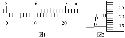
(1)用游标卡尺测得该材料的长度如图1所示,其示数__________  ,用螺旋测微器测得该材料的直径如图2所示,其示数
__________ 。
(2)为了减小实验误差,并要求在实验中获得较大的电压调节范围,在测量其电阻时应选择的电路是图3中的___________ 。
A.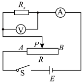 B.
B. 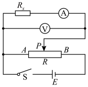
C.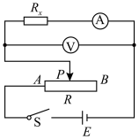 D.
D. 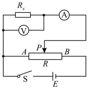
(3)该同学连接电路和操作均正确,从实验原理上看,待测电阻测量值会____________ 其真实值(选填“大于”“小于”或“等于”)。
(4)某次实验中电流表和电压表的示数分别为 和
和 ,用所测得的物理量符号和已知物理量的符号(导电材料长度
 、直径
、直径 )表示该材料的电阻率
__________ 。
的电阻率,现提供以下实验器材:A. 20分度的游标卡尺
B. 螺旋测微器
C. 电流表
(量程为、内阻约为);D. 电压表
(量程为、内阻约为);E. 滑动变阻器
(,额定电流为);F. 直流电源
(电动势为,内阻很小)G. 导电材料
(长约为,电阻约为);H. 开关一只、导线若干。
请回答下列问题:
(1)用游标卡尺测得该材料的长度如图1所示,其示数
,用螺旋测微器测得该材料的直径如图2所示,其示数。(2)为了减小实验误差,并要求在实验中获得较大的电压调节范围,在测量其电阻时应选择的电路是图3中的
A.
B. C.
D. (3)该同学连接电路和操作均正确,从实验原理上看,待测电阻测量值会
(4)某次实验中电流表
和电压表的示数分别为和,用所测得的物理量符号和已知物理量的符号(导电材料长度、直径)表示该材料的电阻率
您最近一年使用:0次
实验题
|
适中
(0.65)
【推荐3】某同学通过实验测定一个阻值约为5Ω的电阻Rx的阻值。
(1)现有直流电源(电压为4V)、滑动变阻器(0~50Ω,额定电流2A)、开关和导线若干,以及下列电表:
A.电流表(0~0.6A,内阻约0.125Ω)
B.电压表(0~3V,内阻约3kΩ)
为减小测量误差,实验电路应采用如图中的_______ (选填“甲”或“乙”)。
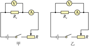
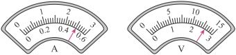
(2)接通开关,改变滑动变阻器滑片P的位置,并记录对应电流表示数I、电压表示数U。某次电表示数如图所示,可得该电阻的测量值Rx= =
=_______ Ω。(保留两位有效数字)
(3)若在(1)问中选用甲电路,产生误差的主要原因是_______ 。
A.电流表测量值小于流经Rx的电流值
B.电流表测量值大于流经Rx的电流值
C.电压表测量值小于Rx两端的电压值
D.电压表测量值大于Rx两端的电压值
(1)现有直流电源(电压为4V)、滑动变阻器(0~50Ω,额定电流2A)、开关和导线若干,以及下列电表:
A.电流表(0~0.6A,内阻约0.125Ω)
B.电压表(0~3V,内阻约3kΩ)
为减小测量误差,实验电路应采用如图中的
(2)接通开关,改变滑动变阻器滑片P的位置,并记录对应电流表示数I、电压表示数U。某次电表示数如图所示,可得该电阻的测量值Rx=
=(3)若在(1)问中选用甲电路,产生误差的主要原因是
A.电流表测量值小于流经Rx的电流值
B.电流表测量值大于流经Rx的电流值
C.电压表测量值小于Rx两端的电压值
D.电压表测量值大于Rx两端的电压值
您最近一年使用:0次