1 . 在测量金属丝的电阻率的实验中,下列操作正确的是( )
| A.用刻度尺测量金属丝全长,且测量三次,算出其平均值,然后再将金属丝接入电路中 |
| B.用螺旋测微器测金属丝测量一次直径就可以 |
| C.用伏安法测电阻时,采用电流表内接法,多次测量后算出平均值 |
| D.实验中应保持金属丝的温度不变 |
您最近一年使用:0次
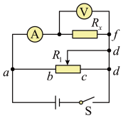
2 . 为测量某金属丝的电阻率,某同学设计了如图甲所示的实验电路图。
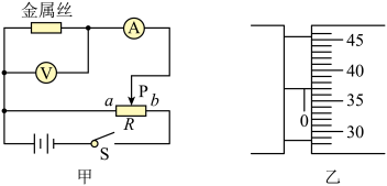
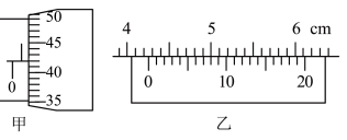
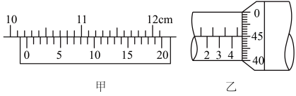
(1)该同学首先用米尺测出接入电路中金属丝的长度L,再利用螺旋测微器测量金属丝直径,测量结果如图乙所示,金属丝直径的测量值
 。
。
(2)为使闭合开关时,电压表、电流表示数均为零,滑动变阻器的滑片P应置于
(3)利用伏安法测该金属丝的电阻R,代入关系式
 等表示)。
等表示)。
(4)由于电表内阻的影响,实验会产生
您最近一年使用:0次
2023-02-17更新
|
179次组卷
|
3卷引用:广东省揭阳市揭东区2022-2023学年高二上学期期末教学质量监测物理试题
广东省揭阳市揭东区2022-2023学年高二上学期期末教学质量监测物理试题(已下线)专题04 实验—测量金属丝的电阻率-【好题汇编】备战2023-2024学年高二物理上学期期末真题分类汇编(粤教版2019,广东专用)广东省揭阳市揭西县2023-2024学年高二上学期1月期末考试物理试题
名校
3 . 某同学通过实验测定一个阻值约为20Ω的电阻Rx的阻值。
(1)现有电源(12V,内阻忽略不计)、滑动变阻器(0~50Ω,额定电流2A)、开关和导线若干,以及下列电表:
A.电流表(0﹣3A,内阻约0.01Ω)
B.电流表(0﹣0.6A,内阻约0.05Ω)
C.电压表(0﹣3V,内阻约600Ω)
D.电压表(0﹣15V,内阻约3kΩ)
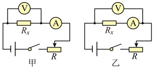
为减小测量误差,在实验中,电流表应选用___________ ,电压表应选用 ___________ (选填器材前的字母);实验电路应采用图中的 ___________ (选填“甲”或“乙”)。
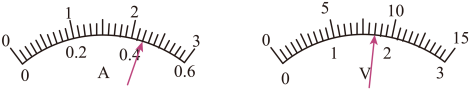
(2)实验中记录电表示数如图所示,可得该电阻的测量值Rx=___________ Ω。(保留三位有效数字)
(3)本实验中选用电路产生系统误差的主要原因是___________ 。
A.电流表的分流作用 B.电流表的分压作用
C.电压表的分流作用 D.电压表的分压作用
(1)现有电源(12V,内阻忽略不计)、滑动变阻器(0~50Ω,额定电流2A)、开关和导线若干,以及下列电表:
A.电流表(0﹣3A,内阻约0.01Ω)
B.电流表(0﹣0.6A,内阻约0.05Ω)
C.电压表(0﹣3V,内阻约600Ω)
D.电压表(0﹣15V,内阻约3kΩ)
为减小测量误差,在实验中,电流表应选用
(2)实验中记录电表示数如图所示,可得该电阻的测量值Rx=
(3)本实验中选用电路产生系统误差的主要原因是
A.电流表的分流作用 B.电流表的分压作用
C.电压表的分流作用 D.电压表的分压作用
您最近一年使用:0次
2023-02-15更新
|
246次组卷
|
5卷引用:广东省河源市龙川县第一中学2022-2023学年高二上学期期末物理试题
名校
4 . 在“测定金属丝的电阻率”的实验中:
(1)用螺旋测微器测量金属丝的直径,其示数如图甲所示,则该金属丝直径的测量值d=________ mm.
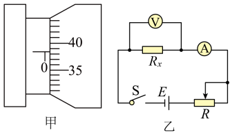
(2)按图乙所示的电路图测量金属丝的电阻Rx(阻值约为15 ),实验中除开关、若干导线之外还提供下列器材:
电压表V(量程0~3V,内阻约3k);
电流表A(量程0~200mA,内阻约3);
滑动变阻器R1(0~50);
滑动变阻器R2(0~200);
电源E(3V,内阻不计)。
为了调节方便,测量准确,实验中滑动变阻器应选________ 。(填写器材的名称符号)
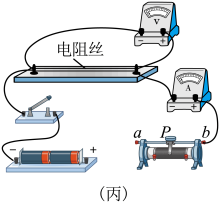
(3)请根据如图乙所示的电路图,用笔画线代替导线将图丙中的实验器材连接起来,并使滑动变阻器的滑片P置于b端时接通电路后的电流最小________ 。

(4)若通过测量可知,金属丝的长度为l,直径为d,通过金属丝的电流为I,对应金属丝两端的电压为U,由此可计算得出金属丝的电阻率 =
=________ 。(用题目所给字母和通用数学符号表示)
(1)用螺旋测微器测量金属丝的直径,其示数如图甲所示,则该金属丝直径的测量值d=
(2)按图乙所示的电路图测量金属丝的电阻Rx(阻值约为15
),实验中除开关、若干导线之外还提供下列器材:电压表V(量程0~3V,内阻约3k
);电流表A(量程0~200mA,内阻约3
);滑动变阻器R1(0~50
);滑动变阻器R2(0~200
);电源E(3V,内阻不计)。
为了调节方便,测量准确,实验中滑动变阻器应选
(3)请根据如图乙所示的电路图,用笔画线代替导线将图丙中的实验器材连接起来,并使滑动变阻器的滑片P置于b端时接通电路后的电流最小
(4)若通过测量可知,金属丝的长度为l,直径为d,通过金属丝的电流为I,对应金属丝两端的电压为U,由此可计算得出金属丝的电阻率
=
您最近一年使用:0次
5 . 某同学在实验室测量一新材料制成的圆柱体的电阻率。
(1)用螺旋测微器测量其横截面直径,示数如图甲所示;用游标卡尺测其长度,示数如图乙所示。则读数结果正确的是( )
(2)圆柱体的电阻R0大约为20Ω。实验用伏安法测此合金材料电阻的实验中,除待测合金材料外,实验室还备有的实验器材如下:
①电压表V1(量程3V,内阻约为3kΩ) ②电压表V2(量程15V,内阻约为15kΩ)
③电流表A1(量程100mA,内阻约为10Ω) ④电流表A2(量程0.6A,内阻约为2Ω)
⑤滑动变阻器R1(0~5Ω) ⑥滑动变阻器R2(0~200Ω)
⑦电动势为3V的电源,内阻不计 ⑧开关S,导线若干
该实验要求待测电阻两端的电压能从0开始调节。为准确测量其电阻,电压表、电流表、滑动变阻器应选:对应器材前的序号组合为:( )
(3)根据所选器材和电压的调节要求,该实验应该选取以下哪个电路进行测量( )
(1)用螺旋测微器测量其横截面直径,示数如图甲所示;用游标卡尺测其长度,示数如图乙所示。则读数结果正确的是( )
| A.1.420mm,40.40mm | B.1.420mm,40.4mm |
| C.0.920mm,42.4mm | D.0.920mm,42.40mm |
①电压表V1(量程3V,内阻约为3kΩ) ②电压表V2(量程15V,内阻约为15kΩ)
③电流表A1(量程100mA,内阻约为10Ω) ④电流表A2(量程0.6A,内阻约为2Ω)
⑤滑动变阻器R1(0~5Ω) ⑥滑动变阻器R2(0~200Ω)
⑦电动势为3V的电源,内阻不计 ⑧开关S,导线若干
该实验要求待测电阻两端的电压能从0开始调节。为准确测量其电阻,电压表、电流表、滑动变阻器应选:对应器材前的序号组合为:( )
| A.①④⑤ | B.②③⑥ | C.①③⑤ | D.②④⑥ |
A.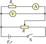 | B. |
C. | D. |
您最近一年使用:0次
实验题
|
适中(0.65)
|
名校
6 . 李同学要测量新材料制成的圆柱体的电阻率ρ,步骤如下:
(1)用游标卡尺测量其长度如图甲所示,由图可知其长度为L=
用螺旋测微器测量其直径如图乙所示,由图可知其直径D=
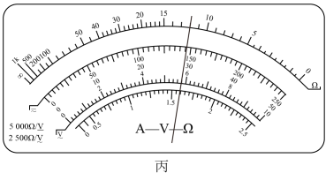
(2)彭同学用多用电表粗测圆柱体的阻值:当用“×100Ω”挡测量时指针偏转角过小,为提高测量的精确度,应换
(3)马同学想用伏安法测量其电阻,设计了一个如图所示的电路图。请你从安全性、精确性等角度评价这一方案,并指出一条该方案可能出现的问题
您最近一年使用:0次
2023-01-13更新
|
274次组卷
|
2卷引用:广东省深圳市福田区福田中学2022-2023学年高三上学期第三次月考物理试题
名校
7 . 在“测定金属的电阻率”的实验中:
(1)用螺旋测微器测量金属丝的直径,其示数如图(甲)所示,则该金属丝直径的测量值__________ mm。

(2)按如图(乙)所示的电路图测量金属丝的电阻 (阻值约为
(阻值约为 )。实验中除开关、若干导线之外还提供下列器材:
电压表V(量程 ,内阻约
,内阻约 );
);
电流表 (量程
(量程 ,内阻约
,内阻约 );
);
电流表 (量程
(量程 ,内阻约
,内阻约 );
);
滑动变阻器 ;
;
滑动变阻器 ;
;
电源E(电动势为 ,内阻不计)。
为了调节方便,测量准确,实验中电流表应选________ ,滑动变阻器应选________ 。(选填器材的名称符号)
(3)请根据图(乙)所示电路图,用笔画线代替导线将图(丙)中的实验器材连线补充完整,并使滑动变阻器的滑片P置于b端时接通电路后的电流最小________ 。
(4)若通过测量可知,金属丝的长度为l,直径为d,通过金属丝的电流为I,金属丝两端的电压为U,由此可计算得出金属丝的电阻率__________ 。(用题目所给字母和通用数学符号表示)
(1)用螺旋测微器测量金属丝的直径,其示数如图(甲)所示,则该金属丝直径的测量值
(2)按如图(乙)所示的电路图测量金属丝的电阻
(阻值约为)。实验中除开关、若干导线之外还提供下列器材:电压表V(量程
,内阻约);电流表
(量程,内阻约);电流表
(量程,内阻约);滑动变阻器
;滑动变阻器
;电源E(电动势为
,内阻不计)。为了调节方便,测量准确,实验中电流表应选
(3)请根据图(乙)所示电路图,用笔画线代替导线将图(丙)中的实验器材连线补充完整,并使滑动变阻器的滑片P置于b端时接通电路后的电流最小
(4)若通过测量可知,金属丝的长度为l,直径为d,通过金属丝的电流为I,金属丝两端的电压为U,由此可计算得出金属丝的电阻率
您最近一年使用:0次
名校
8 . 在测定一根粗细均匀合金丝Rx的电阻率的实验中:
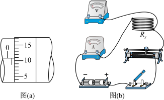
(1)利用螺旋测微器测定合金丝的直径,示数如图(a)所示,则可读得合金丝的直径为___________ mm。
(2)待测合金丝的电阻约为 ,实验室另外还提供的仪器有:
A.电压表V(内阻约为10kΩ,量程为3V)
B.电流表A1(内阻约为3Ω,量程为0.6A)
C.电流表A2(内阻约为0.1Ω,量程为3A)
D.滑动变阻器R(阻值为0~5Ω,额定电流为2A)
E.电源E(电动势为5V,内电阻为1Ω)
F.一个开关、若干导线
①要求较准确地测出其阻值,电流表应选___________ 。(填序号)
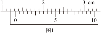
②请根据以上仪器,设计实验电路图,并在图(b)中完成电路图的实物连线_________ ,要求实验时电流表和电压表的示数变化范围尽量大。
(1)利用螺旋测微器测定合金丝的直径,示数如图(a)所示,则可读得合金丝的直径为
(2)待测合金丝
的电阻约为,实验室另外还提供的仪器有:A.电压表V(内阻约为10kΩ,量程为3V)
B.电流表A1(内阻约为3Ω,量程为0.6A)
C.电流表A2(内阻约为0.1Ω,量程为3A)
D.滑动变阻器R(阻值为0~5Ω,额定电流为2A)
E.电源E(电动势为5V,内电阻为1Ω)
F.一个开关、若干导线
①要求较准确地测出其阻值,电流表应选
②请根据以上仪器,设计实验电路图,并在图(b)中完成电路图的实物连线
您最近一年使用:0次
2023-01-09更新
|
225次组卷
|
3卷引用:广东省广州市广雅,省实,二中,六中,执信五校2022-2023学年高二上学期期末联考物理试题
广东省广州市广雅,省实,二中,六中,执信五校2022-2023学年高二上学期期末联考物理试题广东省广州市广东广雅中学2022-2023学年高二上学期期末限时训练物理试题(已下线)专题04 实验—测量金属丝的电阻率-【好题汇编】备战2023-2024学年高二物理上学期期末真题分类汇编(粤教版2019,广东专用)
名校
9 . (1)有一游标卡尺,主尺的最小分度是 ,游标上有20个小的等分刻度。用它测量一小球的直径,如图1所示的读数是
______ 。
(2)用螺旋测微器测量一根金属丝的直径,如图2所示的读数是______ 。

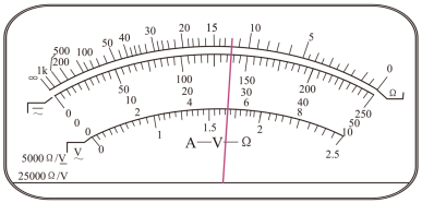
(3)为了测量金属丝的电阻率,某同学先用多用电表粗测其电阻.用已经调零且选择开关指向欧姆挡“ ”挡位的多用电表测量,发现指针的偏转角度太大,这时他应将选择开关换成欧姆挡的“
______ ”挡位(选填“ ”或“
”或“ ”),然后进行
______ ,再次测量电阻丝的阻值,其表盘及指针所指位置如图所示,则此段电阻丝的电阻为______ 。
(4)然后较准确测量金属丝的电阻,除待测金属丝外,实验室还备有的实验器材如下
A.电压表 (量程,内阻约为
 )
)
B.电压表 (量程
(量程 ,内阻约为
,内阻约为 )
)
C.电流表(量程 ,内阻约为
,内阻约为 )
)
D.电流表(量程 ,内阻约为
,内阻约为 )
)
E.滑动变阻器 (
( )
)
F.滑动变阻器 (
( )
)
G.输出电压为 的直流稳压电源E
H.开关S,导线若干
实验中应选用的电压表是__________ ,电流表是__________ ,滑动变阻器是__________ (填器材前序号)
(5)要求实验误差较小,并且电压可以从0开始调节,请在虚线框内设计最合理的电路图_________ 。

,游标上有20个小的等分刻度。用它测量一小球的直径,如图1所示的读数是。(2)用螺旋测微器测量一根金属丝的直径,如图2所示的读数是
。(3)为了测量金属丝的电阻率,某同学先用多用电表粗测其电阻.用已经调零且选择开关指向欧姆挡“
”挡位的多用电表测量,发现指针的偏转角度太大,这时他应将选择开关换成欧姆挡的“”或“”),然后进行。(4)然后较准确测量金属丝的电阻,除待测金属丝外,实验室还备有的实验器材如下
A.电压表
(量程,内阻约为)B.电压表
(量程,内阻约为)C.电流表
(量程,内阻约为)D.电流表
(量程,内阻约为)E.滑动变阻器
()F.滑动变阻器
()G.输出电压为
的直流稳压电源EH.开关S,导线若干
实验中应选用的电压表是
(5)要求实验误差较小,并且电压可以从0开始调节,请在虚线框内设计最合理的电路图
您最近一年使用:0次
名校
10 . 小美同学想通过实验测定一个均匀导体的阻值。
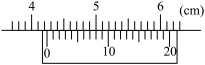
(1)用游标卡尺测量有效长度时,测得的结果如图所示,则长度
_________ mm。在测量电阻时,采用了如下方法:
(2)她先用多用电表的欧姆挡粗测,发现用“ 10”倍率时指针偏角过小,于是需要改“
_________ ”(选填“1”或“100”)倍率,改换倍率后重新测量前还需要将两表笔短接做_________ (填“机械”或“欧姆”)调零;
(3)用改换倍率后的欧姆挡测得待测电阻大致阻值如图,现备有下列器材进行进一步测量:后用伏安法更精确地测量其电阻Rx,要求测量数据尽量精确且电压从零开始增加,可供该同学选用的器材除开关、导线、待测电阻Rx外还有:
A.直流电源(24V)
B.电压表(量程0~15V,内阻约10kΩ)
C.电压表(量程0~50V,内阻约50kΩ)
D.电流表(量程0~10mA,内阻约为100Ω)
E.电流表(量程0~25mA,内阻约为30Ω)
F.滑动变阻器(最大阻值50Ω)
G.开关和导线若干
为了保证实验顺利进行,并使测量误差尽量小,电压表应选_________ ,电流表应选_________ (请填写字母代号);
(4)本实验的测量电路适合用电流表的_________ (填“内”或“外”)接法和滑动变阻器的_________ (填“分压”或“限流”)式接法;
(5)由于电表内阻的影响,Rx的测量值较真实值_________ (填“偏大”、“偏小”或“相等”)。
。(1)用游标卡尺测量有效长度时,测得的结果如图所示,则长度
(2)她先用多用电表的欧姆挡粗测,发现用“
10”倍率时指针偏角过小,于是需要改“(3)用改换倍率后的欧姆挡测得待测电阻大致阻值如图,现备有下列器材进行进一步测量:后用伏安法更精确地测量其电阻Rx,要求测量数据尽量精确且电压从零开始增加,可供该同学选用的器材除开关、导线、待测电阻Rx外还有:
A.直流电源(24V)
B.电压表(量程0~15V,内阻约10kΩ)
C.电压表(量程0~50V,内阻约50kΩ)
D.电流表(量程0~10mA,内阻约为100Ω)
E.电流表(量程0~25mA,内阻约为30Ω)
F.滑动变阻器(最大阻值50Ω)
G.开关和导线若干
为了保证实验顺利进行,并使测量误差尽量小,电压表应选
(4)本实验的测量电路适合用电流表的
(5)由于电表内阻的影响,Rx的测量值较真实值
您最近一年使用:0次
2022-12-14更新
|
441次组卷
|
5卷引用:广东省广州市协和中学2022-2023学年高二上学期期中物理试题