名校
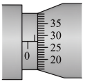
1 . 在测定金属的电阻率实验中,用螺旋测微器测量金属丝的直径d,示数如图所示,读数为__________ mm;
(2)某同学用指针式多用电表粗略测金属丝的阻值。他将红黑表笔分别插入“+”、“-”插孔中,将选择开关置于“×10”档位置,然后将红、黑表笔短接调零,此后测量阻值时发现指针偏转角度较小。试问:
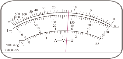
①为减小实验误差,该同学应将选择开关置于“__________ ”位置;(选填“×1”、“×100”)
②再将红、黑表笔短接,重新调零后继续实验,结果看到指针指在如图所示位置,则金属丝电阻的测量值为__________ Ω。
(2)某同学用指针式多用电表粗略测金属丝的阻值。他将红黑表笔分别插入“+”、“-”插孔中,将选择开关置于“×10”档位置,然后将红、黑表笔短接调零,此后测量阻值时发现指针偏转角度较小。试问:
①为减小实验误差,该同学应将选择开关置于“
②再将红、黑表笔短接,重新调零后继续实验,结果看到指针指在如图所示位置,则金属丝电阻的测量值为
您最近一年使用:0次
2023-05-15更新
|
242次组卷
|
5卷引用:广东省广州市七区2021-2022学年高二上学期期末教学质量监测物理试题
广东省广州市七区2021-2022学年高二上学期期末教学质量监测物理试题广东省茂名市信宜市第二中学2021-2022学年高二下学期月考物理试题(一)广东省广州市白云中学2022-2023学年高二上学期期末物理试题(已下线)专题04 实验—测量金属丝的电阻率-【好题汇编】备战2023-2024学年高二物理上学期期末真题分类汇编(粤教版2019,广东专用)(已下线)专题06 实验—练习使用多用电表-【好题汇编】备战2023-2024学年高二物理上学期期末真题分类汇编(粤教版2019,广东专用)
2 . 测定金属丝的电阻率,提供实验器材如下:
A.待测金属丝R(电阻约8Ω)
B.电流表A(0.6A,内阻约0.6Ω)
C.电压表V(3V,内阻约3kΩ)
D.滑动变阻器R1(0-5Ω,2A)
E.电源E(6V)
F.开关,导线若干
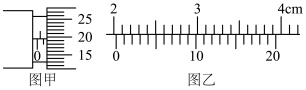
(1)某同学用螺旋测微器和游标卡尺分别测量金属丝的直径和长度,读出图中的示数,图甲为___________  ,图乙为
,图乙为___________ 。
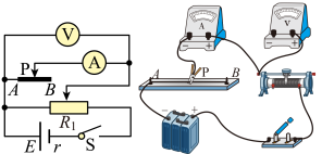
(2)某同学采用如图所示电路进行实验,请用笔画线代替导线,在图中将实物电路图连接完整___________ 。
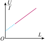
(3)测得金属丝的直径为d,改变金属夹P的位置,测得多组金属丝接入电路的长度 及相应电压表示数
 、电流表示数
 ,作出
,作出 如图所示。测得图线斜率为
 ,则该金属丝的电阻率
 为
为___________ 。
(4)关于电阻率的测量,下列说法中正确的有___________
A.开关 闭合前,滑动变阻器
 的滑片应置于最左端
B.实验中,滑动变阻器的滑片位置确定后不可移动
C.待测金属丝 长时间通电,会导致电阻率测量结果偏小
D.该实验方案中电流表 的内阻对电阻率测量结果没有影响
A.待测金属丝R(电阻约8Ω)
B.电流表A(0.6A,内阻约0.6Ω)
C.电压表V(3V,内阻约3kΩ)
D.滑动变阻器R1(0-5Ω,2A)
E.电源E(6V)
F.开关,导线若干
(1)某同学用螺旋测微器和游标卡尺分别测量金属丝的直径和长度,读出图中的示数,图甲为
,图乙为。(2)某同学采用如图所示电路进行实验,请用笔画线代替导线,在图中将实物电路图连接完整
(3)测得金属丝的直径为d,改变金属夹P的位置,测得多组金属丝接入电路的长度
及相应电压表示数、电流表示数,作出如图所示。测得图线斜率为,则该金属丝的电阻率为(4)关于电阻率的测量,下列说法中正确的有
A.开关
闭合前,滑动变阻器的滑片应置于最左端B.实验中,滑动变阻器
的滑片位置确定后不可移动C.待测金属丝
长时间通电,会导致电阻率测量结果偏小D.该实验方案中电流表
的内阻对电阻率测量结果没有影响
您最近一年使用:0次
名校
3 . 某同学想设计一个测量金属棒电阻率的实验方案,实验室提供的器材有;
A.电压表V(量程0~3V,内阻约为3.0kΩ)
B.电流表 (满偏电流
(满偏电流 ,内阻
,内阻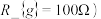
C.电流表 (量程为0.6A,内阻约为0.4Ω)
D.定值电阻
E.滑动变阻器R(0~5Ω,允许通过的最大电流为2A)
F.干电池组(电动势为6V,内阻约为0.05Ω)
G.一个开关和导线若干
H.螺旋测微器,游标卡尺
(1)用多用电表粗测金属棒的阻值:当用“×10Ω”挡时发现指针偏转角度过大,他应该换用__________ 挡(填“×1Ω”或‘ ,换挡并进行一系列正确操作后,指针静止时如图甲所示,则金属棒阻值约为
__________ Ω。
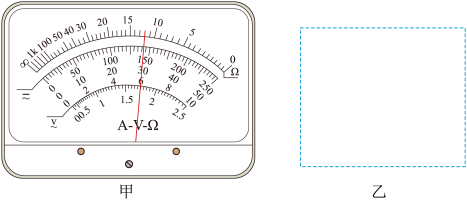
(2)请根据提供的器材,设计一个实验电路,要求各电表的示数超过满刻度的一半,尽可能精确测量金属棒的阻值,请在图乙所示的虚线方框中画出电路图_____________ 。
(3)若实验测得电流表示数为 ,电流表示数为
 ,则金属棒电阻为
 =
=___________ (用、、 、
、 表示)。
表示)。
A.电压表V(量程0~3V,内阻约为3.0kΩ)
B.电流表
(满偏电流,内阻C.电流表
(量程为0.6A,内阻约为0.4Ω)D.定值电阻
E.滑动变阻器R(0~5Ω,允许通过的最大电流为2A)
F.干电池组(电动势为6V,内阻约为0.05Ω)
G.一个开关和导线若干
H.螺旋测微器,游标卡尺
(1)用多用电表粗测金属棒的阻值:当用“×10Ω”挡时发现指针偏转角度过大,他应该换用
,换挡并进行一系列正确操作后,指针静止时如图甲所示,则金属棒阻值约为(2)请根据提供的器材,设计一个实验电路,要求各电表的示数超过满刻度的一半,尽可能精确测量金属棒的阻值,请在图乙所示的虚线方框中画出电路图
(3)若实验测得电流表
示数为,电流表示数为,则金属棒电阻为=、、、表示)。
您最近一年使用:0次
2023-05-03更新
|
1023次组卷
|
2卷引用:2023届广东省深圳市高级中学高三下学期三模物理试题
名校
4 . 某小组设计了图甲所示的实验电路,用来研究稀盐水溶液的电阻率与浓度的关系。图中 为开关,
为开关, 为单刀双掷开关,为待测稀盐水溶液液柱。
(1)实验时,闭合之前应将的滑片P置于______ (填“C”或“D”)端。
(2)实验时,闭合,置于位置1,改变滑动变阻器滑动触头P的位置,电流表示数有明显变化,电压表没有示数;再将置于位置2,情况相同。经检查,电路中所有元件完好,则导线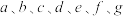 中出现断路故障的是
______ 导线。
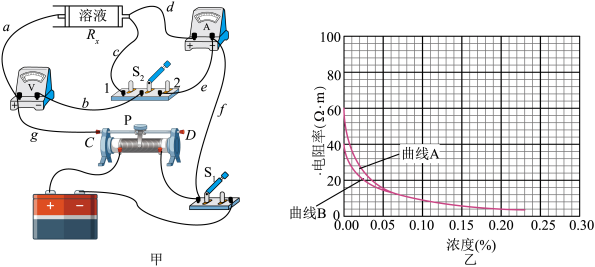
(3)修复故障后,用电流表内接法测量的阻值时应该将置于位置______ (填“1”或“2”)。
(4)用电流表内、外接法得到的电阻率随浓度变化的两条曲线如图乙所示(不计由于通电导致的化学变化)。某次用电流表内接法测得的阻值为 ,的横截面积为
 ,长度为
,长度为 ,则其电阻率为
______  ,由图乙中对应曲线
______ (填“A”或“B”)可得此时溶液浓度约为______ %。
为开关,为单刀双掷开关,为待测稀盐水溶液液柱。(1)实验时,闭合
之前应将的滑片P置于(2)实验时,闭合
,置于位置1,改变滑动变阻器滑动触头P的位置,电流表示数有明显变化,电压表没有示数;再将置于位置2,情况相同。经检查,电路中所有元件完好,则导线中出现断路故障的是(3)修复故障后,用电流表内接法测量
的阻值时应该将置于位置(4)用电流表内、外接法得到
的电阻率随浓度变化的两条曲线如图乙所示(不计由于通电导致的化学变化)。某次用电流表内接法测得的阻值为,的横截面积为,长度为,则其电阻率为,由图乙中对应曲线
您最近一年使用:0次
2023-04-30更新
|
750次组卷
|
5卷引用:2023届广东省广州市黄埔区高三下学期5月三模物理试题
2023届广东省广州市黄埔区高三下学期5月三模物理试题2023届山东省淄博市部分学校高三下学期二模测试物理试题(已下线)14.电学实验-2023年山东二模分类汇编(已下线)第46讲 测定金属丝的电阻率(练习)-2024年高考物理一轮复习讲练测(新教材新高考)(已下线)吉林、黑龙江2024年1月适应性测试物理T12变式题-测量电阻丝电阻率-实验题
名校
5 . 为测量一段长度已知为l、粗细均匀的电阻丝的电阻率,某小组采用了如下实验操作:
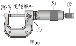
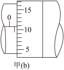
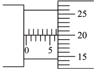
(1)用图甲(a)中的螺旋测微器测量电阻丝的直径d。先将电阻丝轻轻地夹在测砧与测微螺杆之间,当测微螺杆快接近电阻丝时,再旋转___________ (选填“①” “②”或“③”),直到听见“喀喀”的声音为止;利用螺旋测微器测定电阻丝的直径,示数如图甲(b)所示,则可读得直径为d=___________ mm。
(2)用图乙所示电路图测量电阻丝的电阻Rx,其中R0为一定值电阻。请用笔画线代替导线,把图丙中的实物电路补充完整________ 。

(3)第一次按图乙所示的电路测量,调节滑动变阻器的滑片,测得多组电压U及电流I的值;第二次将电压表改接在a、b两点测量,测得多组电压U及电流I的值,并作出如图丁所示的U-I图像。则第一次测量得到的图线是________ (选填“M”或“ N”),由图像可得电阻丝的电阻Rx=________ Ω,最后,根据电阻定律可求得电阻丝的电阻率ρ=_______ 。(用Rx、d、l及常量π表示)

(1)用图甲(a)中的螺旋测微器测量电阻丝的直径d。先将电阻丝轻轻地夹在测砧与测微螺杆之间,当测微螺杆快接近电阻丝时,再旋转
(2)用图乙所示电路图测量电阻丝的电阻Rx,其中R0为一定值电阻。请用笔画线代替导线,把图丙中的实物电路补充完整
(3)第一次按图乙所示的电路测量,调节滑动变阻器的滑片,测得多组电压U及电流I的值;第二次将电压表改接在a、b两点测量,测得多组电压U及电流I的值,并作出如图丁所示的U-I图像。则第一次测量得到的图线是
您最近一年使用:0次
名校
6 . 现有一合金制成的圆柱体,为测量该合金的电阻率,现用伏安法测圆柱体两端之间的电阻,用螺旋测微器测量该圆柱体的直径,用游标卡尺测量该圆柱体的长度.螺旋测微器和游标卡尺的示数如图(a)和(b)所示。
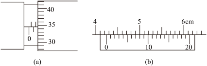
(1)圆柱体的直径为________ mm,长度为________ cm。
(2)已知实验中所用的滑动变阻器阻值范围为0~10Ω,电流表内阻约几欧,电压表内阻约20kΩ。电源为干电池(不宜在长时间、大功率状况下使用),电动势E=4.5V,内阻很小。则以下电路图中___________ (填电路图下方的字母代号)电路为本次实验应当采用的最佳电路。但用此最佳电路测量的结果仍然会比真实值偏___________ (填“大”或“小”)。
A.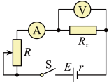 B.
B.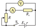
C.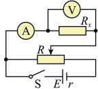 D.
D.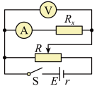
(3)若流经金属丝的电流为I,圆柱体两端之间的电压为U,圆柱体的直径和长度分别为D、L,测得D、L、I、U表示的电阻率的关系式为ρ=________ 。
(1)圆柱体的直径为
(2)已知实验中所用的滑动变阻器阻值范围为0~10Ω,电流表内阻约几欧,电压表内阻约20kΩ。电源为干电池(不宜在长时间、大功率状况下使用),电动势E=4.5V,内阻很小。则以下电路图中
A.
B.C.
D.(3)若流经金属丝的电流为I,圆柱体两端之间的电压为U,圆柱体的直径和长度分别为D、L,测得D、L、I、U表示的电阻率的关系式为ρ=
您最近一年使用:0次
2023-04-23更新
|
658次组卷
|
5卷引用:广东省汕头市潮阳区河溪中学2022-2023学年高二上学期期中物理试题(等级考)
名校
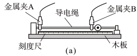
7 . 实验小组测量某弹性导电绳的电阻率。实验过程如下:
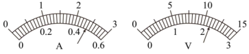
装置安装和电路连接。如图(a)所示,导电绳的一端固定,另一端作为拉伸端,两端分别用带有金属夹A、B的导线接入如图(b)所示的电路中。先闭合开关S1、S2,调节R,使电压表和电流表的指针偏转到合适的位置,记录两表的示数U0和I0。
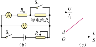
(1)然后断开开关S2,电流表的示数
(2)多次拉伸导电绳,每次都测量并记录AB间的距离L和导电绳横截面积S,调节滑动变阻器R的滑片的位置,使电流表的示数为I0,记下此时的电压表示数U。绘制如图(c)所示的图像。已知图线的斜率为k、与纵轴的截距为d,则弹性导电绳的电阻率ρ==
(3)若考虑电流表的内阻,则(2)中的电阻率的测量值
您最近一年使用:0次
2023-03-31更新
|
2256次组卷
|
8卷引用:2023届广东省东莞实验中学高三下学期一模物理试题
2023届广东省东莞实验中学高三下学期一模物理试题2023届广东省肇庆中学高三下学期强化训练模考一物理试题广东省中山市华侨中学2023-2024学年高三下学期模拟卷(三)物理试题2023届湖北省十一校高三下学期第二次联考物理试题(已下线)物理-2023年高考押题预测卷01(全国乙卷)四川省成都七中八一学校2022-2023学年高三下学期6月高考适应性考试理综物理试题(已下线)2023年辽宁卷物理T12-测量电阻丝电阻率-实验题重庆市第七中学2023-2024学年高二上学期半期考试物理试题
名校
8 . 欲用伏安法测定一段阻值约为5Ω左右的金属导线的电阻,要求测量结果尽量准确,现备有以下器材
A.电池组(3V,内阻1Ω)
B.电流表(0~3A,内阻约0.0125Ω)
C.电流表(0~0.6A,内阻约0.125Ω)
D.电压表(0~3V,内阻约3kΩ)
E.电压表(0~15V,内阻约15kΩ)
F.滑动变阻器(0~20Ω,额定电流1A)
G.滑动变阻器(0~2000Ω,额定电流0.3A)
H.开关、导线
(1)上述器材中应选用的是______ ;(填写各器材的字母代号)
(2)设实验中,电流表电压表的某组示数如下图所示,图示中I=______ A,U=______ V
(3)为使通过待测金属导线的电流能在0~0.5A范围内改变,电流表应采用______ (填“外接法”或“内接法”),滑动变阻器应采用______ (填“分压接法”或“限流接法”)。请将下图中给定的器材连成实验电路____ 。

A.电池组(3V,内阻1Ω)
B.电流表(0~3A,内阻约0.0125Ω)
C.电流表(0~0.6A,内阻约0.125Ω)
D.电压表(0~3V,内阻约3kΩ)
E.电压表(0~15V,内阻约15kΩ)
F.滑动变阻器(0~20Ω,额定电流1A)
G.滑动变阻器(0~2000Ω,额定电流0.3A)
H.开关、导线
(1)上述器材中应选用的是
(2)设实验中,电流表电压表的某组示数如下图所示,图示中I=
(3)为使通过待测金属导线的电流能在0~0.5A范围内改变,电流表应采用
您最近一年使用:0次
9 . 实验室为同学们测定金属丝的电阻率准备了如下器材:

电源:电压为3V;
电流表 :0~0.6A量程,内阻约为0.3Ω;
电流表 :0~3A量程,内阻约为0.1Ω;
电压表V:0~3V量程,内阻约为3kΩ;
滑动变阻器:最大阻值为5Ω;
待测镍铬合金丝:电阻约为10Ω;
一个开关,导线若干。
(1)为了尽可能准确地进行测量,电流表应该选择__________ 。
(2)要求尽可能测量多组数据,请按照要求完成实物图的连接__________ 。
(3)开关闭合前,滑动变阻器的滑片应该置于__________ (填“A”或“B”)端。
电源:电压为3V;
电流表
:0~0.6A量程,内阻约为0.3Ω;电流表
:0~3A量程,内阻约为0.1Ω;电压表V:0~3V量程,内阻约为3kΩ;
滑动变阻器:最大阻值为5Ω;
待测镍铬合金丝:电阻约为10Ω;
一个开关,导线若干。
(1)为了尽可能准确地进行测量,电流表应该选择
(2)要求尽可能测量多组数据,请按照要求完成实物图的连接
(3)开关闭合前,滑动变阻器的滑片应该置于
您最近一年使用:0次
名校
10 . 用欧姆表粗测得一圆柱复合材料的电阻约为3kΩ,某实验小组通过以下实验测量其电阻率ρ。
(1)该实验小组用刻度尺测量其长度L、螺旋测微器测量其直径D,某次直径测量结果如图所示:D=______ mm;
(2)实验使用的滑动变阻器的阻值为0~20Ω,请将如图实际测量电路补充完整______ 。
(3)闭合开关前,滑动变阻器的滑片应置于______ 端(填“a”或“b”);
(4)某次实验时,电压表的示数为U,电流表的示数为I,用实验测量的物理量L、D、U、I表示电阻率,则表达式为ρ=______ 。
(1)该实验小组用刻度尺测量其长度L、螺旋测微器测量其直径D,某次直径测量结果如图所示:D=
(2)实验使用的滑动变阻器的阻值为0~20Ω,请将如图实际测量电路补充完整
(3)闭合开关前,滑动变阻器的滑片应置于
(4)某次实验时,电压表的示数为U,电流表的示数为I,用实验测量的物理量L、D、U、I表示电阻率,则表达式为ρ=
您最近一年使用:0次
2023-03-02更新
|
1171次组卷
|
10卷引用:广东省广州市黄埔区2022-2023学年高二上学期期末教学质量监测物理试题
广东省广州市黄埔区2022-2023学年高二上学期期末教学质量监测物理试题(已下线)专题04 实验—测量金属丝的电阻率-【好题汇编】备战2023-2024学年高二物理上学期期末真题分类汇编(粤教版2019,广东专用)广东省惠州市龙门县高级中学2023-2024学年高二上学期12月月考物理试题广西梧州市藤县第六中学2022-2023学年高二下学期3月月考物理试题云南省红河哈尼族彝族自治州屏边苗族自治县第一中学2022-2023学年高二上学期期末物理试题云南省曲靖市宣威市第三中学2022-2023学年高二下学期第二次月考物理试题山西省临汾市洪洞县向明中学2023-2024学年高二上学期第一次月考物理试题(B卷)山西省临汾市洪洞县向明中学2023-2024学年高二上学期第一次月考物理试题(A卷)青海省西宁市海湖中学2023-2024学年高二上学期第二次阶段考试物理试题天津市南开区2023-2024学年高三上学期阶段性质量检测物理试卷(二)